
Integration of LoRaWAN Transceiver in The Things Stack (TTS)
LoRaWan (Long Range Wide Area Network), created by Semtech, uses a proprietary radio technology and enables to transmit data packets via radio free of charge in the license-free SDR/ISM 868 MHz band. With this technology in the sub-GHz range with significantly lower free space attenuation, impressive ranges of up to several kilometers are sometimes achieved (dependent on the antenna or antenna gain). This article explains the installation of this MakerKit for LoRaWAN, the configuration as well as the complete integration in the TTS (The Things Stack V3). You will find more information on this topic here: Set up LoRaWAN P2P Connection Transceiver Receiver.
MakerKit conversion
The available MakerKit can be modified so that two full-fledged LoRaWAN modules can send data to the TTN via a LoRa gateway.
Create a Things Stack account / Enter/generate data for the radio module
To communicate with LoRa radio modules via TTS, an account in The Things Stack must be created.
Hint: TTN is not recommended, when the migration on V3 is ongoing. (legacy / old standard)
- Call the cluster picker: The Things Network Cluster Picker
- Select Europe 1 on the world map or follow this link: The Things Network Account
- After the installation, the configuration can be made on the frontpage:
-
 Select Applications.
 -
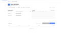
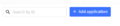 Select the following tab --> add application
 -
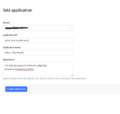 Then enter the application ID/description as you see fit, see example below. Then confirm by clicking Create Application.


Example: description
- Application ID : my-lora-modules
- Application name: my-lora-module-pool
- Description: All my LoRa modules are listed here... Sampletext
Now, the application is set up. We are located in the overview / Application overview. Now, the LoRa radio module / sensor must be registrated (0 End Devices at the moment).
-
 Now the end devices/LoRa modules must be set up. Select +Add end device.
 -
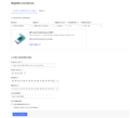 Now define the LoRa board from the MakerKit in TTS.


In this example, the following settings are used:
'''Select End Device :'''

Brand --> Heltec Automation

Model --> Wifi LoRa 32 (V2) Class A ABP

Hardware Version --> leave on Unknown

Firmware Version --> auf 1.0

Profile Region --> EU_863-870 Mhz
'''Enter registration Data'''

Frequency plan --> Europe 863-870 Mhz (SF9 for RX2 -recommended)

Device Address: generate

ApplicationSessionKey AppSky: generate

NetworkSessionKey NwkSky: generate
-
 End device ID: my-new-device
 -
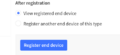 Confirm with Register End Devices.
 -
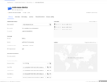 The new device is now fully created. An overview of the device is displayed.


Required keys
We need the following keys from this surface to authenticate the device correctly later:
- Device Address
- NetworkSessionKey
- ApplicationSessionKey
Hint: These keys will be required later when programming the LoRa module. These are required in msb format. With the <> symbol, it can be adapted to fit alongside AppSKey, for example.
In this example, the extracted data, that will be important, is listed:
| Device Address | 260BB744 |
| NetworkSessionKey | 0xDC, 0x5D, 0xA2, 0xD6, 0xFB, 0x78, 0x9A, 0x9E, 0xC6, 0x00, 0x9D, 0xBD, 0xA6, 0x5E, 0x6C, 0xE3 |
| ApplicationSessionKey | 0x6E, 0xB3, 0xC4, 0x6F, 0x38, 0x2C, 0xD8, 0xB7, 0x61, 0x89, 0xD1, 0x87, 0xDE, 0xB9, 0x79, 0xB6 |
Assembly/Configuration of LoRa transmitter
This paragraph shows the setup of a node to TTN communication. Here, a LoRa controller obtains values from a sensor (Air pressure, humidity, and temperature). Data packages are periodically forwarded/pushed via radio to the TTN for further processing via a LoRa gateway.
Overview of following contents
In the following, you will find a summary of the mentioned contens of further paragraphs from this article:
- Schematic structure of the controller
- communication between two ESP32 controller LoRa WAN
- set up development environment
- addressing additional sensors attached to the controller (In the example, there is a barometric sensor BME 280, which supplies the values about air pressure (also altimeter) temperature and humidity)
- how data packages are transmitted from the transceiver via gateway in the TTN
- decoding of data in TTN
Important hint for commissioning
When starting up (including during tests), it is essential to connect the 868 MHz antenna beforehand, as the radio module could be damaged by overload if no antenna is connected.
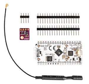
Used components
The LoRa Board Heltec V2 with ESP32 CPU is used.
- radio technologies:
- LoRa
- WiFi
- BLE (Bluetooth Low Energy)
- 0.96 Zoll OLED display (is controlled in this example)
ESP32 Board specification
This paragraph shows technical specifications in a tabular presentation.

| components | characteristics |
|---|---|
| ESP32 controller | |
| WiFi |
|
| Bluetooth |
|
| LoRa Chip | |
| connections |
|
| More characteristics | |
| measurements | 50.2 x 25.5 x 9.74 mm |
| power consumption measured |
|

| front |
|
| Backside |
Setup LoRa transceiver
This paragraph shows the housing structure of both devices that can also be used as LoRa transceiver. The board with the supplied antenna can be connected directly with the U.FL / IPEX antenna connector on the PCB.
LoRa transceiver
The LoRa transceiver consists of the following components:
- BME 280
- 868 MHz antenna
- housing
Housing
For the housing for LoRa transceiver, there are also STL files, which you will find at the end of this article.
- LoRa_Case_Transceiver_Cover.stl
- LoRa Case_Transceiver_Body.stl
Later, the board with the supplied antenna can be connected directly with the U.FL / IPEX antenna connector on the PCB. When using the available screw holes, very short screws must be used. To connect the barometric sensor for initial testing without assembly, it can be connected/soldered to the board as follows (see flying setup):

Hint: For later use of the board in the custom case, it is advisable to solder the cables from the BME directly to the front rather than to the back as shown here. Please note how the cable was installed in the housing further down.
Contact/Scheme
The following scheme shows the correct contacting of the circuit board. Hint: A small drop of hot glue fixes the supply lanes on the BM280.
ESP LoRa32         <---->          BME 280 Sensor


Contacts:


PIN 15           <------->         SCL
PIN 4            <------->         SDA
GND              <------->         GND
3.3V+            <------->         VIN
Assembly
The following procedure is valid for the correct assembly of the sensor:
- The antenna cable (without creases) is to be placed around the round recesses.
- Measure the supply line so that it is just long enough, so that the antenna is optimally stored.
Installation of software components
The previous paragraph showed the configuration of the hardware (LoRa transceiver).
Now, we will show how to install and setup the required software components.
Setup of the development environment Arduino IDE
To increase the compatibility to other systems to maintain it "as simple as possible", it was done without the compilation in the Linux shell.
The treatment of choice is the Arduino IDE that is available for Linux as well as Windows for free.[1]
In the article, the further procedure refers on the setup on Ubuntu Linux.
Setup of the board ESP32 / Arduino IDE
As the DevBoard of the IDE is unknown, the information must be made available via link.
The following link will be entered under "Additional Board Manager URLs" (see below)
-
 Go to File → Preferences → Settings and enter the following URL: https://dl.espressif.com/dl/package_esp32_index.json
 -
 After that, the board group can be installed. Go to Tools → Board → Board Manager, search for esp32, and install it.
 -
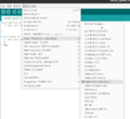 Select the appropriate Heltec board: Heltec Wifi LoRa (V2) The ESP32 board is now set up.


Overview of required libraries
To use all additional characteristics, the following libraries are available:
- Library OLED Display
- Library BME 280 Sensor
- Library LoRa WAN MCCI-catena functionality
Setup of the library OLED display
Search for the following current library: Adafruit bme 280
-
 Adafruit BME280 Library, the Adafruit Unified Sensor library is automatically installed.

Adjustment of PinMappings
Please note that the original PinMapping does not agree with the board. For this, a file must be configured, which is stored in the Arduino directory. The file location may vary depending on the installation type or version of the basic installation:
- /.arduino15/packages/esp32/hardware/esp32/1.0.6/variants/heltec_wifi_lora_32_V2/pins_arduino.h
Please search for the following entries in the file:
static const uint8_t SDA = 21;

static const uint8_t SCL = 22;
Change SDA and SCL pin assignment to:
static const uint8_t SDA = 4;

static const uint8_t SCL = 15;
After this change, the BME 280 can be addressed by the ESP32 without any problems.
Setup of the MCCI LMIC library for LoRa WAN functionality
Search for the MCCI LMIC library (version 4.0 was used in the test):
-
 Select the MCCI LoRaWAN LMIC Library here (currently 4.0.0)

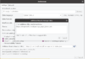
After installation of the Library, adjustments in the Config must be made. Radio frequencies are set to US standard by default. For this, the European ISM tapes are required:
Storage location: ..Arduino/libraries/arduino-lmic-master/project_config/lmic_project_config.h
Since the file may also be located differently in the file system depending on the type of installation, we use the file search function.
This is made on Linux with the following command:
find / -path /proc -prune -false -o -name lmic_project_config.h
-
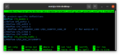 Set the right EU setting here #define CFG_eu868 (see PIC) and comment out the US Config.

Setting up the LoRa Transceiver / Program code for the use with TTN The Things Network
After all libraries are available in the Arduino IDE, the adjusted program (see below ( program code) is loaded into the Arduino (Drag&Drop)

Simply enter or replace the generated data from the TTS in the program code, for example:
| Device Address | 260BB744 |
| NetworkSessionKey | 0xDC, 0x5D, 0xA2, 0xD6, 0xFB, 0x78, 0x9A, 0x9E, 0xC6, 0x00, 0x9D, 0xBD, 0xA6, 0x5E, 0x6C, 0xE3 |
| ApplicationSessionKey | 0x6E, 0xB3, 0xC4, 0x6F, 0x38, 0x2C, 0xD8, 0xB7, 0x61, 0x89, 0xD1, 0x87, 0xDE, 0xB9, 0x79, 0xB6 |
Download the program code for the integration in TTS: LoRaWAN-Demo-Thomas-Krenn
Flashing process
- To do this, connect the fully assembled LoRa transceiver to the computer via Micro USB/USB.
- Select the suitable port, which is for Linux based operating systems often /dev/ttyUSB0.
- Then, the software is directly flashed with the help of the Arduino IDE on ESP.
Commissioning
In the previous paragraphs, the device was prepared and is now ready for use. The commissioning is shown in the following paragraph.
-
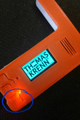
 After starting and displaying the Thomas-Krenn logo
 -
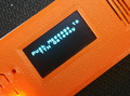
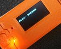 Reads the temperature, humidity, and air pressure values from the BME 280 sensor at regular intervals of 60 seconds. (To prevent temperature deviations, measurements are only taken every 60 seconds.)
 -
 The LoRa WAN packet is then processed and sent via LoRaWAN.
 -
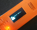 Data is being sent.
 -
 Between measurements, the board is put into DeepSleep mode. From this point on, the OLED remains permanently switched off to save energy and avoid distorting the values.
 -
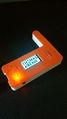
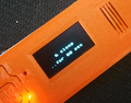
 If a frame is to be sent manually with a display message, this can be initiated using the button at the bottom left / display.


Verification of data in TTS / The Things Stack
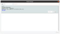
If everything worked, the data should now arrive in TTN under Application / Device / Live Data.
-
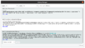
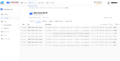 In the Live View, you can see that the data appear in TTS. The payload display only shows hexadecimal values.

Convert payload appropriately
The payload containing the temperature, air pressure, and humidity values is in hexadecimal form. Therefore, a simple decoder is required to convert it into plain text.
- Select the Formatter type, as presented in the following screenshot.
-
 Applications -> Payload -> Formatter -> Downlink. Select Formatter Type: javascript.

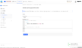
- Go to Applications -> Payload Formatters -> Uplink -> Default uplink payload formatter.
- Enter the following code at Formatter type: javascript Formatter parameters:
function Decoder(bytes, port) {

   return {

     Test values: String.fromCharCode.apply(null, bytes)

  };

  // Simple conversion from Hex to ASCII

}
- Safe changes with the SAVE CHANGES button.
-
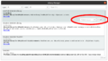
 Decode Payload from HEX to ASCII. If the decoder is working correctly, the payload transmitted in the TTS can now be decoded correctly in the console.
- Payload decoded
Now, the payload is suitable decoded: '''30.91C | 34.91 % | 978.17 mB'''
Temperature: 30.91 C°
humidity: 34.91 %
air pressure: 978.17 mBar
These values may be processed further via further broker.
3D cases for Receiver/Transceiver Module
You can download 3D cases with all housing components in STL format for slicing or printing from Thomas-Krenn: LoRa_Cases.zip
-
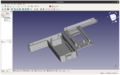 FreeCAD model of the housing parts.

Troubleshooting FAQs
The LoRaWAN Troubleshooting FAQ article, provides a collection of solutions if problems appear during installation and configuration.
Test environment
Key data of the environment:
- Thomas-Krenn LES plus
- Ubuntu 20.04 LTS 64-bit
- Kernel: Linux ubuntu 5.4.0-40-generic
References
- ↑ Software Arduino (arduino.cc)
 |
Author: Wilfried Seifert Wilfried Seifert, working in the Systems Engineering department at Thomas-Krenn, is responsible for system/prototype development in his work area. LPIC 3 certified, deals with construction / programming of embedded / GPIO systems; in his spare time he likes to repair old home computers, attends Linux conferences or is on the road with his bike (MTB) for sporting compensation.
|
 |
Translator: Alina Ranzinger Alina has been working at Thomas-Krenn.AG since 2024. After her training as multilingual business assistant, she got her job as assistant of the Product Management and is responsible for the translation of texts and for the organisation of the department.
|